| Pipe Size (and class) | Hole Size | Preferred Boot (all from Press Seal) | Alternative (from Trellborg) | Notes |
|---|---|---|---|---|
| 50 PVC | 203mm (8") | 8 QRS PSX:DD (Step) | none | |
| 75 PVC | 203mm (8") | 8 QRS PSX:DD (Step) | none | |
| 100 PVC | 203mm (8") | 8 QRS PSX:DD (Step) | none | |
| 125 PVC (DR 28-35) | 203mm (8") | 08-11 PSX:DD | "10-06 PSX:DD from Press Seal” | 10-06 alternative needs a 10” hole. NOTE: PSX 08-05:DD are obsolete and not interchangable with 08-11’s. |
| 150 PVC (DR 14-35) | 305mm (12") | 12-06 PSX:DD | S106-12BWS | |
| 200 PVC (DR 28-35) 200 PVC (DR 14-35) | 305mm (12") | 12-08 PSX:DD 12M PSX:DD | 106-12AWS S106-12WS | |
| 250 PVC (DR 14-35) | 356mm (14") | 14M PSX:DD | S106-14AWS | |
| 300 PVC (DR 14-25) 300 PVC (DR 28-35) | 406mm (16”) | 16M PSX:DD | S106-16WS | |
| 350 PVC (DR 18-25) | 508mm (20") | 20Y PSX:DD | S106-20BWS | |
| 375 PVC (DR 28-35) | 508mm (20") | 20Y PSX:DD | S106-20BWS | |
| 450 PVC (DR 18-25) | 610mm (24") | 24L PSX:DD | S206-24A | |
| 450 PVC (DR 28-35) | 559mm (22") | 22M PSX:DD | S206-24A | NOTE: S206-24A alternative needs a 24" hole. |
| 500 PVC (DR 18-25) | 660mm (26") | 26L PSX-2:DD | S206-24L | NOTE: S206-24L alternative needs a 24" hole. |
| 525 PVC (DR 28-35) | 660mm (26") | 26L PSX-2:DD | S206-26 | |
| 600 PVC (DR 18-25) | 762mm (30") | 30L PSX-2:DD | S206-30 | |
| 600 PVC (DR 28-35) | 711mm (28") | 28A PSX-2:DD | S206-28 | |
| 300 RCP | 559mm (22") | 22L PSX-2:DD | S206-20L | |
| 375 RCP | 610mm (24") | 24A PSX-2:DD | S206-24L | |
| 450 RCP | 711mm (28") | 28A PSX-2:DD | S206-28 | |
| 525 RCP | 813mm (32”) | 32L PSX-2:DD | S206-32 | Both boots require an 1500mm MH minimum. S306-32 option will work in a 1200mm MH. |
| 600 RCP | 914mm (36”) | 36A PSX-2:DD (needs 1800mm MH) | S206-34L (needs 1500mm MH) | NOTE: S206-34L alternative needs a 34” hole S306-34L option will work in a 1200mm MH. |
| 675 RCP | 1016mm (40”) | 40L PSX-2:DD (needs 1800mm MH) | S206-38L (needs 1800mm MH) | NOTE: S206-38L alternative needs a 38” hole S306-38L option will work in a 1500mm MH. |
| 750 RCP | 1067mm (42") | 42A PSX-2:DD | S206-42 | Both boots require an 1800mm MH minimum. |
Details
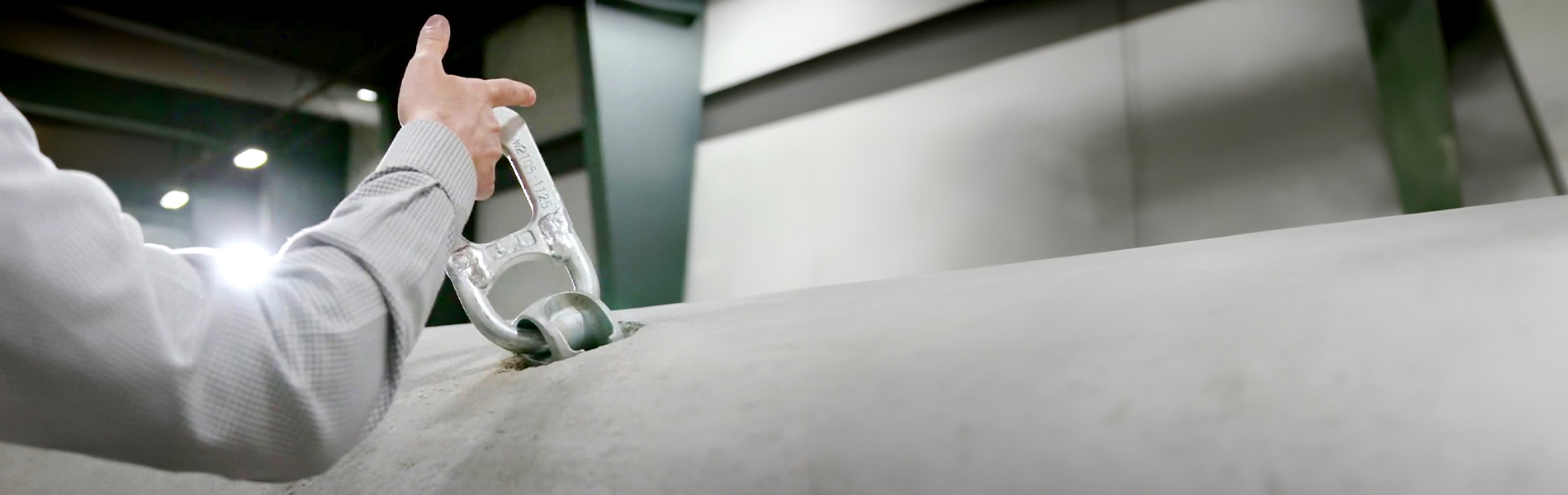
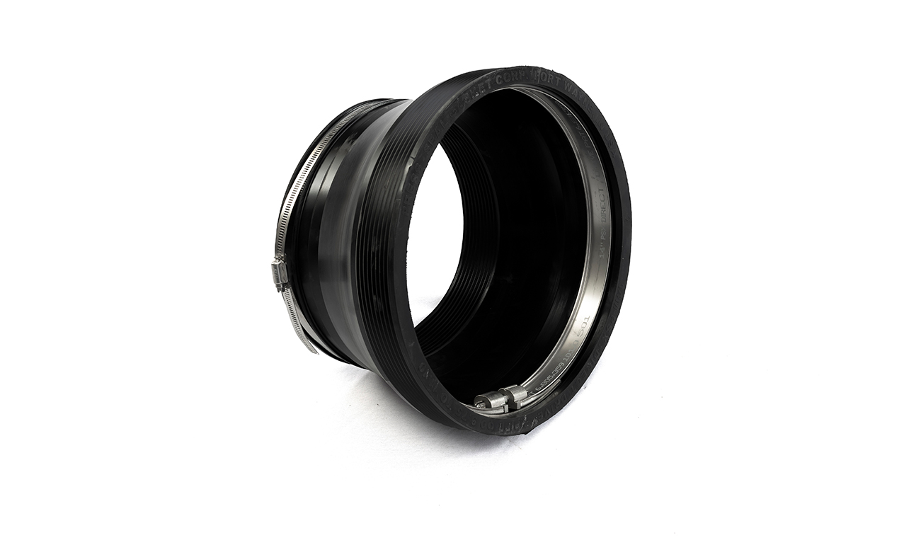
The rubber boot type connector is a common method of connecting both concrete and other pipe materials to maintenance holes, providing both a flexible and watertight connection. The boot connector ranges in sizes to suit the pipe outside diameter and also the maintenance hole diameter that the pipe is to be installed into.
Contact the MCON engineering department for further details on this connector or other connecting systems that are available.
PIPE INSTALLATION PROCEDURE:
- Clean pipe and boot to ensure no dirt or foreign materials are present.
- Clamping surface on pipe must be clean and smooth.
- Center pipe in opening and insert pipe until it breaks the inside plane of maintenance hole or, if maintenance hole is benched, to the invert ledge of benching.
- Attach take-up clamp(s) and stagger screw(s) of clamps around the groove of the gasket so that take-up pressure will be equalized. Make sure each clamps is completely in the correct groove.
- Using a torque ratchet or torque wrench, gradually tighten screw(s) of clamp(s) in an alternating pattern to 12 ft-lbs (for 8”-14” holes), 20 ft-lbs (for 16”-20” holes), or 60 ft-lbs (for 22” holes and larger).
- After reaching the recommended torque from Note 5 on the final screw, check all screws again to ensure compression of the clamps.
- Adjust pipe to line and grade.